TM 5-3895-374-24-1
SENSOR MOUNTING
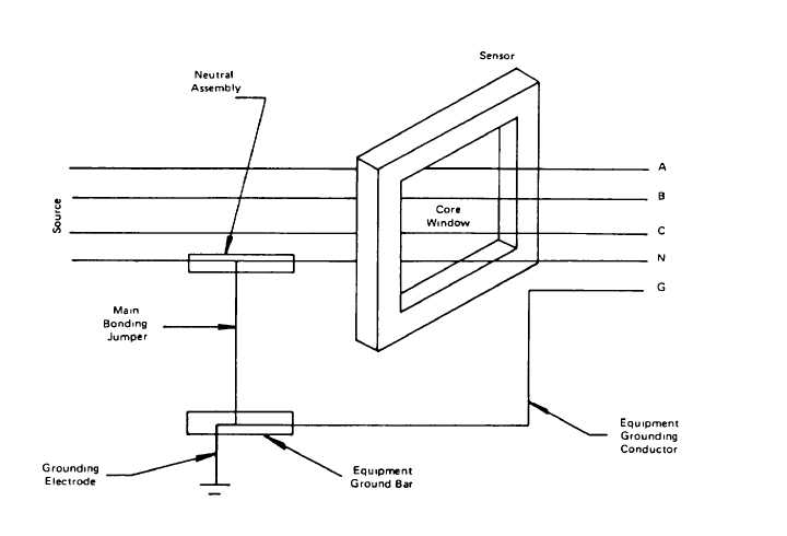
The Sensor should be mounted so that all phase and neutral (if used) conductors pass through the Core Window once
The Equipment Grounding Conductor (If used) must not pass through the Core Window. The neutral conductor must be
free of all grounds after passing through the Core Window (Figure 3)
FIGURE 3
When so specified by the system design engineer, the Sensor may be mounted so that only the conductor connecting the
neutral to ground at the service equipment passes through the Core Window In such cases, the Sensor must provide a
signal to the particular Ground Fault Relay which Is associated with the main disconnect
Maintain at least two inches clearance from the Iron core of the Sensor windings to the nearest bus bar or cable to avoid
false tripping. Cable conductors should be bundled securely and braced to hold them at the center of the Core Window.
The Sensor should be mounted within an enclosure and protected from mechanical damage
If the electrical system will be energized at any time prior to completion of the installation, the Sensor output windings must
be short circuited by a jumper across terminals X1, X3 to X2, X4. Remove this jumper when all wiring is completed to the
Ground Fault Relay and the Disconnect Trip Coil.
RELAY MOUNTING
The Ground Fault Relay should be mounted in a vertical position within an enclosure with the terminal block at the lower
end The location of the relay should be such that the trip setting knob is accessible without exposing the operator to
hazard from contact with live parts or arcing from disconnect operation Means have been provided so that the trip setting
can be adjusted from outside the enclosure as shown in Figure 4. To do this, the potentiometer is removed from the
printed circuit board and remounted on the inside back of the box body In the holes provided, with its terminals toward the
terminal block. If needed, a shaft extension is added and knob is adjusted to recommended protrusion.
(page 3-91)