TM 5-3895-374-24-2
THRUST BEARING ADJUSTMENT
1.
Loosen setscrews over outer and inner end caps. Two for H
and HL size pumps, four for all other sizes.
2.
Turn inner end cap clockwise, viewed from shaft end, until it
projects slightly from bracket exposing approximately three
threads.
3.
Turn outer end cap clockwise until rotor is tight against head
and rotor shaft cannot be turned.
4.
Make a reference mark on bracket end, opposite a notch on
outer end cap. Back off outer end cap required number of
notches. See Figure 14.
Each 1/4 travel on circumference of end cap is equivalent to
approximately .0015 inch for all sizes.
5.
End clearances set per Step 4 are adequate for viscosities
up to 750 SSU (SAE 20 lube oil at room temperature).
Higher viscosity liquids require additional end clearances.
As a general guideline, for viscosities between 750 and
7500 SSU (heavier lube oils) double the amount of end
clearance indicated in Step 4; for viscosities between 7500
and 75, 000 SSU (e.g., resins) triple the amount and for
viscosities greater than 75, 000 SSU (e.g., black strap
molasses) use 4 times the amount.
For specific recommendations for end clearances for
viscosity or for operating temperatures above 225 F, check
with your Viking representative or consult the factory.
6.
Tighten inner end cap with a spanner wrench. Tap spanner
wrench lightly but DO NOT OVER TIGHTEN as it will
damage the threads.
7.
Tighten setscrews that hold inner and outer end caps to
prevent their turning in bracket.
8.
Rotor and shaft should turn smoothly by hand one complete
revolution. If rotor and shaft doesn’t turn smoothly, go back
and repeat Thrust Bearing Adjustment Steps 1 thru 8.
TOTAL END CLEARANCE CHART
PUMP
TURN OUTER END CAP
TOTAL
SIZE
COUNTER-CLOCKWISE NO OF
NOTCHES
END CLEARANCE’
H & HL
5
.005
K thru LL
8
.008
*Tot end clearance includes extra clearance for temperature of 40 F
FIGURE 14.
INSTALLATION OF CARBON GRAPHITE
BUSHINGS
When installing carbon graphite bushings, extreme care must be taken
to prevent breaking. Carbon graphite is a brittle material and easily
cracked. If cracked, the bushing will quickly disintegrate. Using a
lubricant and adding a chamfer on the bushing and the mating part will
help in installation. The additional precautions listed below must be
followed for proper installation:
1.
A press must be used for installation.
2.
Be certain bushing is started straight.
3.
Do not stop pressing operation until bushing is in proper
position, starting and stopping will result in a cracked
bushing.
4.
Check bushing for cracks after installation.
Carbon graphite bushings with extra interference fits are
frequently furnished for high temperature operation. These
bushings must be installed by a shrink fit.
1.
Heat bracket or idler to 750° F.
2.
Install cool bushings with a press.
3.
If facilities are not available to reach 750 F temperature, it
is possible to install with 450 F temperature; however, the
lower the temperature, the greater the possibility of cracking
bushing.
Consult factory with specific questions on high temperature
applications. Refer to Engineering Service Bulletin ESB-3.
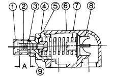
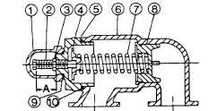
PRESSURE RELIEF VALVE
INSTRUCTIONS
FIGURE 15.
Size H and HL
FIGURE 16.
Size K, KK, L, LO, and LL
LIST OF PARTS
1. Valve Cap
6. Valve Body
2. Adjusting Screw
7. Valve Spring
3. Lock Nut
8. Poppet
4. Spring Guide
9. Cap Gasket
5. Bonnet
10. Bonnet Gasket
page 3-1221