TM 5-3895-374-24-2
ASSEMBLY
Optional Mechanical Seal
(Synthetic Rubber Bellows Type)
Synthetic rubber bellows mechanical seals, the style shown in
Figures 11, 12, & 13, may be installed as alternate to the
standard Teflon seal as the application warrants. These seals
are dependent upon friction to drive them and, therefore, there
are no set screws to tighten. No spacer is used on Model "K"
between rotor and synthetic rubber bellows seal.
Prior to installing rotating portion of mechanical seal, prepare
and organize rotor shaft, head and idler assemblies and
appropriate gaskets for quick assembly.
Once rotating portion of mechanical seal is installed on rotor
shaft, it is necessary to assemble parts as quickly as possible
to insure that seal does not stick to shaft in wrong axial
position. The seal should be expected to stick to the shaft
after several minutes setting time.
Never touch sealing faces with anything except clean hands or
clean cloth. Minute particles can scratch the seal faces and
cause leakage.
1.
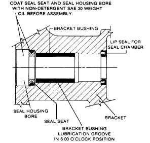
Clean rotor hub and bracket seal housing bore. Make
sure both are free from dirt and grit. Coat outer
diameter of
seal
seat
and
inner
diameter
of
sealhousing bore with nondetergent SAE 30 weight
oil.
2.
Start seal seat in seal housing bore, refer to Figure
11. If force is necessary, protect seal face with a
clean cardboard disc and gently tap it in place with a
piece of wood.
FIGURE 11.
3.
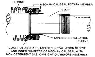
Place tapered installation sleeve on shaft, refer to
Figure 12. Sleeve is furnished with H, HL, K, KK, L,
LQ and LL size replacement mechanical seals. Coat
rotor shaft, tapered installation sleeve and inner
diameter of mechanical seal rotary member with a
generous amount of non-detergent SAE 30 weight oil.
Petrolatum
may
be
used
but
grease
is
not
recommended.
FIGURE 12.
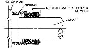
4.
Place seal spring on shaft against rotor hub. Refer to
Figure 13.
5.
Slide rotary member, lapped contact surface facing
away from spring, over installation sleeve on shaft
until it is against spring. Remove seal installation
sleeve.
Do not compress spring.
6.
Coat rotor shaft with non-detergent SAE 30 weight oil.
Start end of shaft in bracket bushing and turn from
right to left, slowly pushing until the ends of the rotor
teeth are just below the face of the casing.
Leave the rotor in this position. Withdrawal of rotor
and shaft may displace the carbon seal rotating face
and result in damage to the seal.
FIGURE 13.
AT
THIS
POINT,
FINISH
ASSEMBLY
PROCEDURES
STARTING AT STEP 10, PAGE 9.
page 3-1220