TM 5-3895-374-24-2
Installation
or shop assembled Conveyors, Units are match marked, and shipped in longest sections practical for shipment. Field
assembly can be accomplished by connecting marked joints and in accordance with packing list and or drawing if
applicable. In field erection, the mounting surfaces for supporting the conveyor must be level and true so there is no
distortion in the conveyor. Shims or Grout should be used when required. Check for straightness as assembly is made.
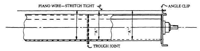
For Conveyor assemblies purchased as parts or merchandise, assemble as follows: Place conveyor troughs in proper
sequence with inlet and discharge spout properly located. Connect the trough flanges loosely. Do not tighten bolts. Align
the trough bottom center-lines perfectly using piano wire (or equivalent) then tighten flange bolts. Tighten all anchor bolts.
Assembly of conveyor screws should always begin at the thrust end. If the thrust end is not designated, assembly should
begin at the drive end. If a thrust end is designated, assemble trough end and thrust bearing. Insert the end, or drive
shaft, in the end bearing. Do not tighten set screws until conveyor assembly is completed.
1.
Place the first screw section in the trough, slipping the end or drive shaft into the pipe end. Secure tightly with
coupling bolts. Install so that conveyor end lugs are opposite the carrying side of the flight.
2.
Place a coupling shaft into the opposite end of conveyor pipe. Tighten coupling bolts.
3.
Slide hanger with bearing over coupling shaft and clamp hanger to trough.
4.
Assemble alternately, conveyor screws, couplings and hangers until all screws are installed repeating steps 1, 2,
and 3.
a)
With Hangers: Assemble screw section so that fighting at each end is approximately 180° from ends of
flighting of adjacent sections. Also, adjust conveyor screw and thrust unit so that hangers are equally spaced
between adjacent screws. After each hanger is installed, rotate the conveyor by hand to insure that no binding
occurs. Remove hanger clamps and bolt hanger to trough with the bearing centered between conveyor screws.
b)
Without Hangers: (close coupled) Assemble screws so that flighting at adjoining ends of screw sections
align to produce a continuous helix surface. (Note coupling holes have been drilled in assembly to allow for flight
alignment.)
5.
The end shaft should be inserted through the trough end bearing/seal into the terminal screw section. Install and
tighten coupling bolts. The bearing and seal should be adjusted to be true and concentric on the shaft and bolts
tightened. If packing gland type seals are used, they should be tightened only enough to prevent leakage. Check
waste pack type seals to insure packing is loose but sufficiently tight to prevent leakage.
page 3 - 748