TM 5-3895-374-24-1
Connections
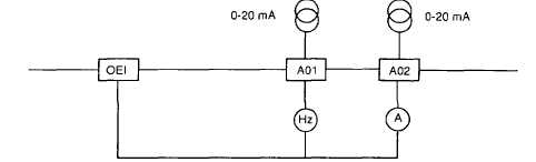
Analogue outputs
The variable speed controller has two 0-20 mA analogue outputs A01 and A02.
The current supplied by these two outputs is proportional to:
- A01 motor frequency,
- A02 motor current.
Maximum output voltage +10 V for a maximum Impedance of 500 W
Scale factor:
- A01:20 mA corresponds to high speed (see settings p 48),
A02:20 mA corresponds to 1,82 times the rated current of the speed controller
(see characteristics) p. 10 and 11)
NOTE
The two analogue outputs can be modified to 4-20 mA and assigned to other variables.
Refer to the 21d part of this document "Special applications’ (p 81)
Wiring precautions
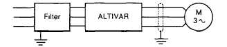
Power
The frequency Inverter emits high frequency electromagnetic waves of low Intensity These
cause interference signals, which may affect the operation of audio-frequency equipment
This Interface can be reduced by screening the motor cables, ensuring a good earth and by
fitting suppressors on the Incoming side of the controller (p 77)
Control
Although the control inputs are protected and filtered, It Is recommended to reduce interference
to a minimum by separating control circuits from power circuits
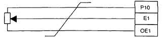
Speed reference
These circuits must be protected against interference signals
The use of twisted cable is recommended, with a pitch of 25 to 50mm.
(page 3-180)