TM 5-3895-374-24-1
TEST PROCEDURES
Field Tests & Monitor Components
The GC-100 Ground Fault Relay and Sensor may be tested with or without tripping as desired. Each Sensor is provided
with a test winding of 800 turns (terminals X5, X6) and should be connected as shown in Figure 2.
The Monitor Components shown in Figure 2 and listed below provide both test with tripping and test without tripping
functions. A nameplate is provided with each Ground Fault Relay giving operation instructions for this connection.
Standard Monitor Components
Test Button
Class 9001
Type K1L-38G-H2
Reset Button
Class 9001
Type K1L-38R-H1
Test Relay
Class 8501
Type RS14, 120 Vac (or Type KP12, 120 Vac)
Relay Socket
Class 8501
Type NR44 (or Type NR1)
To test without tripping, press the Test button only (See Figure 1). This simulates a ground fault in the Sensor,
disconnects the 120 volt power source from the Output Relay K and applies 120 volts to the Control Triac Circuit via L1
After the relay times out the Control Triac Circuit turns on Lamp L1: Some lamp flicker is normal.
To test with tripping, press the Test and Reset buttons simultaneously (See Figure 1). This establishes the normal power
supply connections and energizes the test winding. Both L1 and L2 will light after the time delay interval and the
Disconnect Trip Coil will pick up. Under both test conditions releasing the test button automatically resets the Ground
Fault Relay.
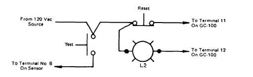
When only the test with tripping function is required, the Monitor Components may be as listed below. Figure 7 shows
connections for these components. No nameplate is supplied for this arrangement.
FIGURE 7
Test With Tripping Monitor Components
Test Button
Class 9001
Type KR-2B-H5
Reset Button
Class 9001
Type K1L-38R-H6
A test operation should be performed at least once a year and once immediately after each time the circuit is interrupted
due to a fault of any kind.
HIGH POTENTIAL TESTS
Do not apply voltage from a megger, hi-pot tester or continuity tester to the solid state time delay ground fault relay circuits.
If a high voltage test is required for the control wiring, remove wires from terminals 11, 12 and 13, then jumper all terminals
together before applying voltage. Do not apply voltage higher than 1,240 Vac RMS/60 Hz. to relay terminals at any time.
(page 3-97)