TM 5-3895-374-24-1
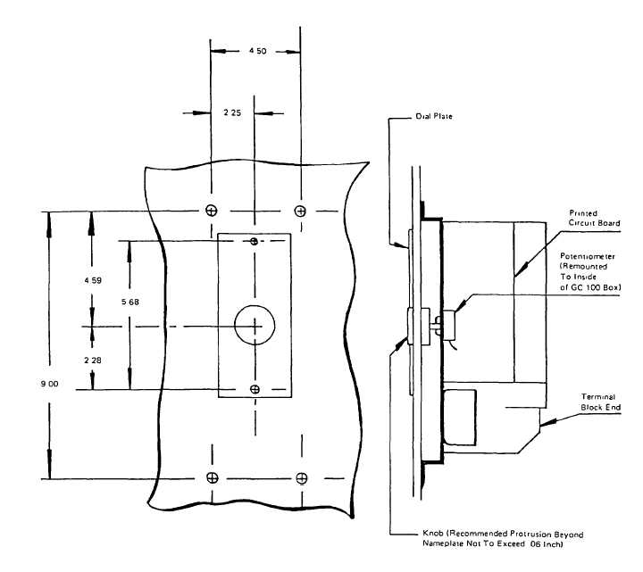
FIGURE 4
CONNECTIONS
Connections for standard application should be made according to the wiring diagram In Figure 2 Wires from the Sensor
to the Ground Fault Relay should be no longer than 25 feet and no smaller than No. 14 AWG. Wires from Monitor
Components should be no longer than 50 feet and no smaller than No 18 AWG Wires 1, 2 and 3 and Control Transformer
should be sized to deliver the necessary current to the Trip Coil at 55% rated output voltage of the Control Transformer.
When zone selective interlock wiring Is used, Ground Fault Relay interconnections should be no smaller than No. 18 and
no longer than 100 feet These wires should be routed separately from any power wiring
All wiring should be protected from arcing fault and physical damage by barriers, conduit, armor or location.
When two wires are used under one terminal on the Sensor, both shall be No. 14.
(page 3-92)

