TM 5-3895-374-24-2
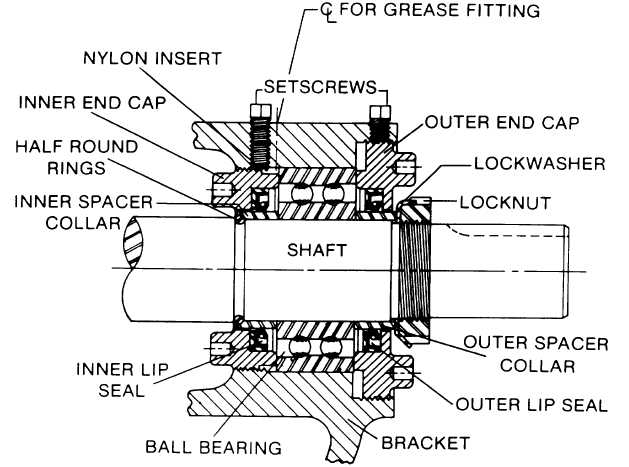
FIGURE 5.
DISASSEMBLY
1.
Mark head and casing before disassembly to insure
proper reassembly. The idler pin, which is offset in
pump head, must be positioned toward and equal
distance between port connections to allow for proper
flow of liquid through pump.
Remove head from pump. Do not allow idler to fall
from idler pin. Tilt top of head back when removing to
prevent this. Avoid damaging head gasket. If pump
is furnished with pressure relief valve, it need not be
removed from head or disassembled at this point.
Refer to Pressure Relief Valve Instructions, page 11.
If pump has jacketed head plate, it will separate from
head when it is removed. The gasket between head
and jacket head plate must be totally removed. Use
new gasket when assembling pump.
2.
Remove idler and bushing assembly.
3.
Insert length of hardwood or brass through port
opening between rotor teeth to keep shaft from
turning. Bend up tang of lockwasher and with a
spanner wrench remove locknut and lockwasher from
shaft.
page 3-1214