TM 5-3895-374-24-2
SECTION 4-TUNING
4.1 CONTROLLER TUNING
This controller has been configured at the factory with input, output and alarm functions to meet your specific
application. Arbitrary alarm and tuning values were used at the factory to allow complete controller checkout. It is
necessary for you-to TUNE this controller to your specific process or machine before going to automatic control. For
tuning, you may use the SELF TUNE feature (Models 2003 and 2004 only) or you may use manual tuning (all models).
In the tune program the PARAM DISPLAY key advances the displays. The LAST key may be used to review the
previous display at any time.
This section provides complete details on all Tuning procedures.
4.2 THE TUNE LOOP
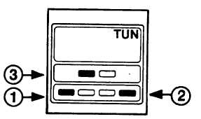
Access to the TUNE loop requires that a special key code be
entered before any Tuning can be done. Press the keys
TUNE-LAST-YES in sequence as shown in Figure 4-1 to
enter the TUNE loop.
A yellow TUN indicator will illuminate on the display when the
code is entered correctly. If the TUN indicator does not
come ON, push the RETURN key and then push the code
again. The PARAM DISPLAY key will advance the displays
in the TUNE loop and the LAST key will back up the displays.
FIGURE 4-1
A flow chart of the TUNE loop is located in Section 7.3 that shows all possible displays in this loop. Your controller will
only show those displays that are appropriate and necessary for your application.
One or two of these displays will appear in sequence when
ALARM 1
TIMER 1
alarms and/or timers have been included. Alarms can be
XXXX UU
XXX:XX
process (display units) or deviation units (i.e., DF for
Deviation Fahrenheit). Timers (Models 2000, 2001 and
OR
2003 only) are set in units of HR:MIN or MIN:SEC up to
999:99 with the time units selected as part of the
ALARM 2
TIMER 2
configuration calibration. Use the arrow keys to set in
XXXX UU
XXX:XX
the desired Alarm or Timer values. Push the PARAM
DISPLAY key to advance to the next display
If setting the alarm or timer relay(s) is the only function you wish to perform in the TUNE loop, push the RETURN key to
return to normal operation.
ECLIPSE INSTRUMENTATION DIVISION
page 3-1094