TM 5-3895-374-24-2
MAN (Flashing)
-
The yellow MAN indicator will flash when the control outputs are OFF as a warning that no
control action is taking place. (Models 2000, 2001 and 2003 only.)
2.4 ALARM/TIMER INDICATORS
The two alarm indicators included in the upper left side of the display appear in red and illuminate "ALM" with either a 1
or 2 or both numbers when either or both alarms/timers are active. The part number specifies each relay action and
type.
The two independent alarms, ALM1 and ALM2, consist of electromechanical relays with both NO and NC contacts on
the rear terminals. The alarm circuitry is active at all times. The alarms continue to function even when the controller
is in the TUNE mode or CAL mode. Timer relay(s), Models 2000, 2001 and 2003 only, begin timing when the START
key is pushed. They automatically reset and time resets to zero when the controller stops or the STOP key is pushed.
2.5 OUTPUT INDICATORS
The two output indicators included in the lower left side of the display appear in blue and illuminate the word "OUT"
with either a I or 2 or both numbers when either or both outputs are ON. (1=Primary output and 2=Secondary output).
With ON/OFF and TPR (Time Proportional) control, the output indicator(s) will cycle ON and OFF as the outputs cycle
ON and OFF. With analog output control, the output indicator(s) will be ON when the output is ON and the
measurement is outside the selected proportional band limits. When the measurement comes within the band limits
the numerical indicator will flash with an ON/OFF ratio proportional to the analog output.
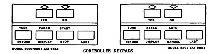
2.6 KEYPAD
The six key membrane type keypad on the front panel is the operator interface. All control, tuning, and recalibration is
performed using the keypad in conjunction with the display. There are no internal jumpers, switches or pots to set or
adjust.
PARAM
The PARAM DISPLAY key advances the displayed information one step at a
DISPLAY
time allowing you to examine and change various system parameters.
The UP arrow key, when pressed, will INCREASE the numeric value of the
displayed parameter. Holding the key in will increase the rate of change
YES
of the parameter. Also use this key to answer YES to a displayed
question "?".
ECLIPSE INSTRUMENTATION DIVISION
page 3-1089