TM 5-3895-374-24-2
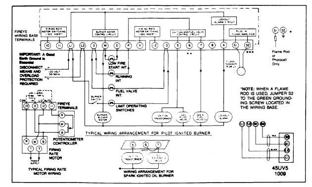
SUGGESTED WIRING DIAGRAM FOR FIREYE EP260, EP261, EP270 PROGRAMMER LOGIC
Caution: All safety limit switches
should be approved as limit controls
and should be wired directly in the
circuit
of
the
Flame
Safeguard
control.
The
use
of
electronic
switches to close interlock circuits
may cause erratic operation.
AUXILIARY DEVICE IN M-D-8 CIRCUIT AT FLAME
MONITOR CONTROL
The function of the low fire start and high fire purge
interlock circuits internally in a new Fireye Flame Monitor
unit is accomplished by highly reliable solid state
electronic circuitry. This prohibits the connection of
power consuming devices (i.e. lamps, annunciators,
relays, timers, etc.) to the D or 8 terminals.
FLAME MONITOR ELECTRICAL NOISE
In applications which appear to have excessive
electrical noise, it may be helpful to add an electrical
noise suppressor to the power supply of the control
circuit.
We recommend the following:
Fireye P/N 60-2333 Line Filter
***When using an infrared scanner (48PT), ground S2 on all EB700’s labeled "ENG. CODE 00.
Subsequent Eng. Code models do not require the ground wire.
page 3 - 1075