TM 5-3895-374-24-2
Safety Shutdown Causes
1.
If pilot flame is not detected during the 10 second trial
for ignition period, the pilot valve and ignition
transformer will be de-energized and the control will
lockout on safety.
2.
If flame is not detected at the end of the main flame
trial for ignition period, all fuel valves will be de-
energized and the control will lockout on safety.
3.
If the main flame fails during a firing cycle, all fuel
valves will be de-energized within 4 seconds after loss
of flame signal and the control will lockout on safety.
4.
If the M-D or 3-P circuits have not closed after a ten
minute wait, a safety lockout will occur and the display
will show an appropriate message.
5.
Manual
reset
is
required
following
any
safety
shutdown.
Description of Functions of Operating Controls
1.
Operating
Controls:
Generally
pressure
or
temperature activated, the operating control closes,
causing the burner startup sequence to begin. When
the operating control opens, the burner shuts off. The
operating control is connected in the L1-13 circuit on
the wiring base.
2.
Limit switches: These are generally pressure, water
level or temperature activated.
a.
Recycle - When it is desired to stop the burner
when the limit switch opens and restart it when
the limit switch recloses, they are connected
between Terminals L1 & 13.
3.
Fuel Valve End Switch Interlock: This is generally
an integral switch mounted on the main fuel valve and
activated by the valve stem. It is connected between
Terminal 3 and 13. The fuel valve end switch interlock
prevents a burner start-up if the valve stem is not in the
"valve closed" position.
NOTE
The use of a Fuel Valve End Switch is
recommended. All FLAME-MONITOR
systems have provision to accept the
Fuel Valve End Switch Interlock. This will
add
additional
safety
to
prevent
hazardous situations.
4.
Running Interlocks: These generally are air flow
switches, high and low fuel pressure switches, oil
temperature switches, atomizing media pressure
switches, and excess smoke density controls. These
interlocks prove proper conditions for normal operation
of the burner. They are wired in series and connected
between Terminals 3 and P.
5.
Low Fire Start Interlock: Generally a firing rate motor
linkage position switch or a damper position switch, will
prove both the linkage and dampers are in their proper
positions to begin burner light off. This switch is
connected between Terminals M and D.
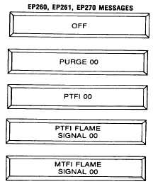
DISPLAY MESSAGES
The FIREYE FLAME-MONITOR does more than control
the burner flame safeguard operation and sequencing. It
provides the operator or serviceman with important burner
information all the time and it remembers a history of the burner
operation.
The following is a complete listing of all the messages
which may be displayed on the FLAME-MONITOR. The
control has an eight character read-out display. Messages that
are greater than eight characters in length will scroll on the
display from left to right.
To gain the full usefulness of the FLAME-MONITOR, do
not reset the control until you are sure of the message
meaning.:
DESCRIPTION
The burner operating control circuit (L1 13) is open and there is power on terminals L1
and L2.
The unit has begun purge, the M terminal has started the blower/burner motor and
the "00" indicates that the control is counting in seconds, up to the end of purge.
The control has begun the pilot trial for ignition sequence. The "00" indicates the
control will count, in seconds, to the end of the PTFI, (unless flame is proven). If
name is proven, note the next message below.
While in PTFI, a flame was sensed and the message changes to include a reading of
the signal strength, designated by "00".
While the main trial for ignition period (MTFI), the display shows a flame signal
reading, designated by "00".
Note: Messages more than 8 characters in length will scroll continuously from right to left on the display.
(page 3 - 1070)