TM 5-3895-374-24-1
Chapter 6
Wiring Your I/O Modules
Wiring Your I/0 Modules
Terminals on the modules have self-lifting pressure plates that accept 2 #14 AWG wires.
Series B 12-point and 16-point and analog modules are equipped with removable terminal
blocks for case of wiring The plug for the removable terminals is also color coded red
(AC), blue (DC), orange (relay), or green (specialty)
LED Indicators on the front of each module display the status of each I/O point The LED
indicators illuminate when the proper signal to an input terminal is applied or when the
processor commands a output to be energized.
To locate the I/O module wiring diagrams, contact your Allen--Bradley sales office for the
latest product data entitled Discrete Input and Output Modules, Publication Number 17462
35 Or, locate the installation instruction sheet that was sent with your I/O module; it also
includes I/O wiring diagrams.
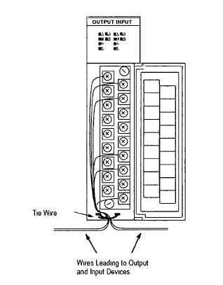
1.
Install a wire tie to secure your wiring and keep it neat (if you feed the tie into one
hole, it will be routed back out through the other.)
2.
Cover any unused slots with card slot fillers (Catalog Number 1746-N2) to keep the
chassis free from debris and dust.
(page 3-423)