TM 5-3895-374-24-1
M-15 Loosen the self-aligning captive saddle screws on
the back plate of the unit.
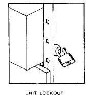
M-16 Withdraw the unit to the point where the bracket in
the right hand of saddle is located between large
and small hole in vertical barrier Padlock can be
placed in the vertical wire trough.
Proceed with unit maintenance Procedure M-25.
Unit Removal
M-17 The Model 4C Motor Control Center was designed
for convenient and quick unit removal and
replacement Use the following procedure for
removal of units.
M-18 Move the operating mechanism to the OFF
position.
M-19 Loosen the knurled thumb screws on the door
(Screws are captive ).
Check for live circuits using a voltmeter and de-
energize any sources of voltage found
M-20 Loosen the self-aligning captive saddle screws on
the
back plate of the unit
(Page 3-135)