TM 5-3895-374-24-1
BENCH TEST PROCEDURE
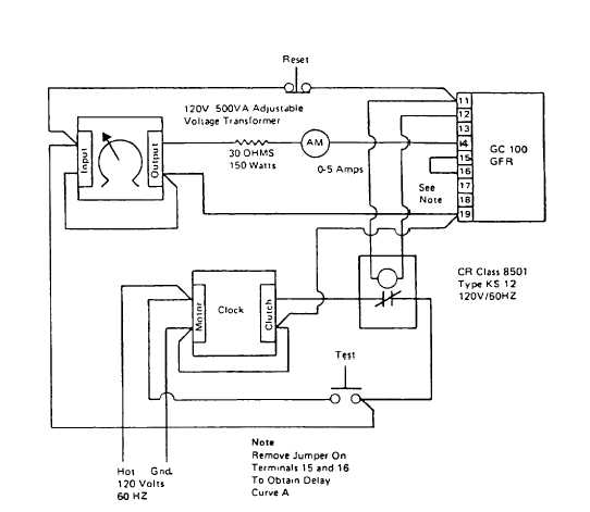
The test bench circuit shown in Figure 8 will permit measurement of both the trip current and the time delay of the relay.
Do not attempt to run this test with the relay mounted In or wired to any other equipment. The trip current may be
measured by increasing the current read by the ammeter, AM, very slowly with the adjustable voltage transformer, and
noting the lowest current at which the relay CR picks up. Multiply the ammeter reading by 600 to get the value which
would be required in the primary of the Sensor to provide the same trip point. Hold the Test button closed while measuring
the trip current, but not more than 30 seconds. The measured trip current should be within ±20% of the nameplate setting.
For determination of the time delay, set the relay trip setting at 1,200 amperes, hold the Test button closed and adjust the
transformer for an ammeter reading of 1.0 amperes (equivalent to 600 amperes Sensor primary current). Then set the
Ground Fault Relay trip setting back to 100 amperes. Measure the relay time delay by pushing the Test button and holding
it until the clock stops. The measured trip time should be within + 5% and - 20% or -3 cycles of the time delay shown in
Figure 6. For measurement of time delay Curve A remove jumper connecting terminal 15 to terminal 16.
FIGURE 8
(page 3-98)

