TM 5-3895-368-14&P
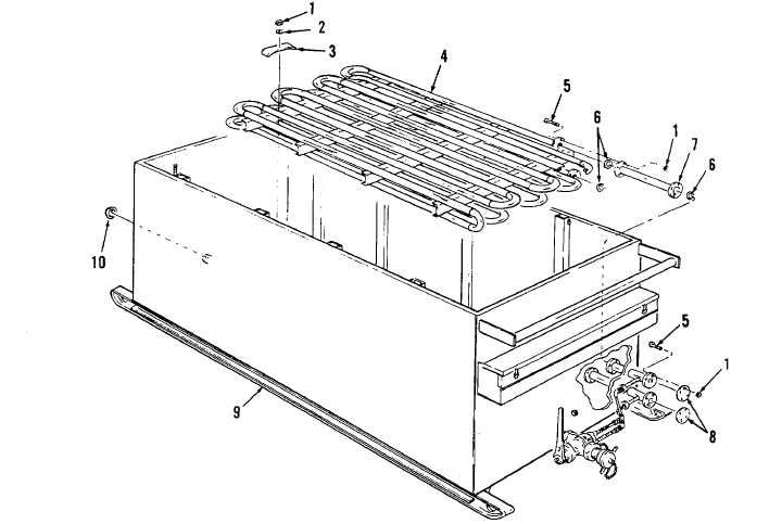
1. Nut (4)
2. Washer (4)
3. Holddown Bar (4)
4. Heater Coil
5. Capscrew (20)
6. Gasket (3)
7. Pipe Assembly
8. Cover (2)
9. Storage Tank
10. Pipe Cape
Figure 4-1. Storage Tank and Heater Coil.
b. During operation, periodically inspect all hot oil
piping connections for signs of leakage. Asphalt cement
must be drained from the tank to the three piping
connections inside storage tank. Tighten all leaking
connections or replace ring gasket(s) as required.
c. The three, 2-inch gate valves (7, Figure 2-3)
used in the hot oil piping, are each equipped with stem
packings. Tighten packing nut, if signs of oil leakage is
evident around the stem.
d. Should there be signs of oil contaminating the
asphalt cement, first check the three hot oil piping
connections inside the storage tank. If no leakage is
evident, inspect for broken weld on coil piping inside the
storage tank or tunnel. Tighten flange bolts or weld
piping as necessary.
e. For disassembly of melter for repair or parts
replacement refer to figures 2-2 through 2-12 for parts
relationship
and
remove
and
replace
defective
component.
f. Replace storage tank heating coil (4, Figure 4-1)
as follows:
(1)
Drain storage tank (paragraph 4-1).
(2)
Remove four holddown bars (3, Figure
4-1).
(3)
Remove eight bolts and nuts which secure
coil connector pipe (7), and remove the
connector pipe and two ring gaskets (6).
4-2