TM 5-3895-374-24-2
FORM 741E
S u r e - F l e x ®
C o u p l i n g s
I n s t a l l a t i o n I n s t r u c t i o n s
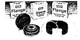
Sure-Flex flanges (outer metallic parts) and sleeves
(inner elastomeric members) come in many sizes and
types. First, determine the size and type of components
being used. Remove all components from their boxes,
and loosely assemble the coupling on any convenient
surface. (Do not attempt to install the wire ring on the
two-piece E or N sleeve at this time.) Also check
maximum RPM values in Table 2 against operating
speed. All rubber sleeves (EPDM and Neoprene) have
the same ratings for a given size and may be used
interchangeably. However, because rubber and Hytrel
sleeves have completely different ratings, they never
should be used interchangeably.
1 Inspect all coupling components and remove any
protective coatings or lubricants from bores, mating
surfaces and fasteners. Remove any existing burrs, etc.
from the shafts.
2 Slide one coupling flange onto each shaft, using snug-
fitting keys where required. With the Type B flange, it
may be necessary to expand the bore by wedging a
screwdriver into the saw cut of the bushing.
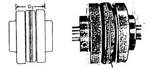
3 Position the flanges on the shafts to approximately
achieve the G1 dimension shgwn in Table 2. It is usually
best to have an equal length of shaft extending into each
flange. Tighten one flange in its final position. Refer to
Table; 1 for fastener torque values. Slide the other far
enough away to install the sleeve. With a two-piece
sleeve, do not move the wire ring to its final position;
allow it to hang loosely in the groove adjacent to the
teeth, as shown.
4 Slide the losse flange on the shaft until the sleeve is
completely seated in the teeth of each flange, (The "G1"
dimension is for reference and not critical.) Secure the
flange to the shaft using the torque values from Table 1.
TABLE 1 - FASTENER TORQUE VALUES (ft.-lbs.)
TYPE J
TYPE S
TYPE B
TYPE SC*
TYPE C
4Hex Head
1Setscrew
1Setscrew
Coupling
2Setscrews
2Setscrews
3Hex Head
Cap Screws
over Keyway
Clamping
over
Size
at 90
at 90
Cap Screws
Flange t o Hub
in Hub
Screws
Keyway
3
3
...
...
...
...
...
...
4
3
...
...
5 ½**
13
...
...
5
7
13
...
4
13
...
...
6
13
13
5
9
13
15
13
7
13
13
5
9
13
30
13
8
23
23
9
18
23
55
13
9
...
23
9
31
23
55
13
10
...
23
15
50
50
130
13
11
·
23
30
75
50
130
13
12
...
50
60
150
100
250
13
13
...
100
75
150
165
...
...
14
...
100
75
150
165
...
...
16
...
100
135
150
165
...
...
*Torque values app!y to hub size when different than flange size.
**Value for socket head clamping screw.
page 3 - 869