TM 5-3895-374-24-2
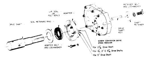
Fig. 1-Assembly.
NOTE:
A Screw Conveyor Drive consists of three sub-
assemblies listed below.
1.
Reducer-Includes speed reducer, shaft retainer,
retainer bolt and lockwasher.
2.
Adapter
Assembly-Includes
adapter
bolts,
lockwashers, a lip type seal, 2 braided type seals and seal
retaining ring.
3.
Drive Shaft-Includes shaft and key.
Make certain none of the parts have been damaged in
shipment. Any shipping damage should be promptly reported
to the carrier. Read all instructions in this manual before
attempting to assemble or install the Screw Conveyor Drive. It
is important that assembly be performed in the following
sequence and that each step be completed before continuing
to the next.
ASSEMBLY
1. Place reducer on blocks that it lays flat with the input shaft
down.
2. Position adapter on reducer output hub so that small end
(end with 12 holes) rests on reducer. Select the 4 mounting
holes to match the shaft used (See Fig. 1). Note: "A"
adapters used on SCXT1 and SCXT2 reducers with 1-1/2"
drive shafts have only 4 holes on the small end.
3. Place adapter screws and lockwashers thru adapter and
thread into reducer. Do Not Tighten.
4. Select either lip type or braided type seals and install as
follows:
Lip Type Seals. Place seal in adapter so that spring faces
out. Seal should be tapped evenly into place in the adapter
with a soft hammer, applying force only on the outer corner of
the seal. Fill cavity between lips of seal with grease. Install
seal retainer ring by tapping with a hammer. Apply grease to
adapter section of shaft (middle section). Slide shaft,
keyseated end first, into adopter and thru reducer. Note: Be
extremely careful when sliding adapter section of shaft
thru seal to prevent seal lips from being damaged or
rolled over.
Braided type seals. Flatten both seals with a soft hammer.
Place seals in adapter, one on top of the other with joints
offset from each other. Lay retaining ring loosely on top of
seals. Slide shaft, keyseated end first, into adapter and thru
reducer. Take care to clear the seals with the adapter section
of the shaft. Once shaft has bottomed, seat retainer ring
by simultaneously hitting the face of the ring on opposite
sides of the shaft with two hammers.
5. Carefully place reducer on its side. Rotate shaft to
align keyseats in shaft and output hub and install key.
install shaft retainer, lockwasher and bolt. Tighten bolt to
torque specified in table 3 on page 5.
6. Lay reducer on blocks with input shaft down and
tighten adapter bolts to torque specified in table 3 on
page 5.
7. If waste packing is to be used it may be installed thru
access hole provided in the adapter. Waste packing, not
furnished with the Screw Conveyor Drive, may be used
as a separate seal option or in combination with either
the lip or braided seals.
INSTALLATION
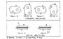
1. Determine the running position of the Screw
Conveyor Drive. Running positions are shown in fig. 2.
Note that the reducer is supplied with 7 plugs; 5 around
the sides of the reducer for horizontal installations and 1
on each face for vertical installations. These plugs must
be arranged relative to the running position as follows:
Horizontal Installations-Install the magnetic drain plug
in the hole closest to the bottom of the reducer. Throw
away the tape that covers the filler/’ventilation plug in
shipment and install plug in topmost hole. Of the 3
remaining plugs on the sides of the reducer, the lowest
one is the minimum oil level plug.
Vertical Installations-Install the filler/’ventilation plug in
the hole provided in the top face of the reducer housing.
Use the hole in the bottom face for the magnetic drain
plug. Of the 5 remaining holes on the sides of the
reducer, use a plug in the upper housing half for the
minimum oil level plug.
Fig. 2-Mounting Positions.
page 3-781