TM 5-3895-374-24-1
Read All Instructions Carefully Before Assembling
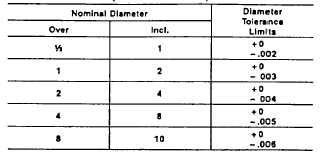
Shaft Tolerance Limits for Adapter Mountings
(Values in Inches)
(page 3-586)
Mounting Procedure for SKF
Split-Housing Pillow Blocks
Assembly
Instructions
for
SKF
Spherical
Roller
Bearings (Adapter Mounting)
Stabilizing rings that are included may or may not be
required at assembly. “Held” bearings require
stabilizing rings while “Free” bearings must not use
stabilizing rings. CAUTION: Do not remove slushing
compound from bearing as It will mix with any
petroleum grease or oil.
Step #1. Check Shaft Tolerance
Step #2. (Fig. 1) Inner Triple Seal
Slide inboard triple seal on shaft This seal will slide freely
into position.
Step #3. (Fig. 2) Adapter Sleeve - Clean Bore & O. Dia.
Position adapter sleeve on shaft. threads outboard as
indicated, to approximate location with respect to required
bearing centerline. Micronized or powdered (not flaked)
graphite or light oil applied to the sleeve outside diameter
surface, results min easier bearing mounting and removal.
Step #4. (Fig. 3) Unmounted Radial Internal Clearance
Measure the unmounted radial internal clearance In the
bearing by inserting progressively larger feeler blades the
full length of the roller between the most vertical unloaded
roller and the outer ring sphere. Do not roll the feeler
blade through the clearance. slide it through. Record the
measurement of the largest size blade that will slide
through. This is the unmounted radial internal clearance.
Step #5. (Fig. 4) Bearing - Clean Bearing Bore
Mount bearing on adapter sleeve, starting with the large
bore of the inner ring to match the taper of the adapter.
With the bearing hand tight on the adapter, locate bearing
to the proper axial position on the shaft (Do not apply
lockwasher at this time because drive up procedure may
damage lockwasher) Step #6. (Fig. 5) Locknut
Apply the locknut with the chamfered face toward the
bearing
Use a lubncant on the threads and face of the locknut
where it contacts the inner ring face of the bearing to
make easier mounting for larger sizes LARGER SIZE
BEARINGS
WILL REQUIRE A HEAVY DUTY SPANNER WRENCH
AND SLEDGE HAMMER TO OBTAIN THE REQUIRED
REDUCTION IN RADIAL INTERNAL CLEARANCE. Do
not attempt to tighten the locknut with hammer and drift.
The locknut will be damaged and chips can enter the
bearing in larger bearing sizes It will be Impossible to
tighten the locknut far enough with a drift It lower hall of
housing is in position, support the shaft such that the
bearing outer ring Is free to rotate. This will prevent
Internal damage to the bearing during tightening of the
locknut. Remeasure internal radial clearance at this time
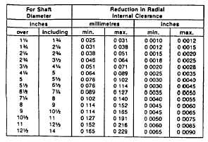
Tighten locknut and measure radial Internal clearance
with feeler blades between the most vertical unloaded
roller and the outer ring sphere or at the 6 00 position if
the bearing is hanging free on the shaft, until the radial
internal clearance Is less than the measurement in Step
3 by the amount shown in the following tabulation:
EXAMPLE: Determine the amount to reduce the radial
internal clearance for a 37/6e
diameter
shaft
mounting:
A. Unmounted radial Internal clearance from Step 3 was
0102 mm (0.004”).
B. Reduction In radial Internal clearance from above
table is a minimum of 0046 mm (00018") and a
maximum of 0064 mm (0.0025”).
C. Final mounted radial Internal clearance will range
from:
Minimum
Maximum
0102 mm (0 004,)
0102 mm (0 004”
-0 064 mm (0 0025')
-0 046 mm (0 00188”)
0 038 mm (0 0015")
0 056 mm (0 0022”)
Step #7. (Flg. 6) Locknut and Lockwasher
Remove locknut and mount lockwasher on adapter
sleeve with inner prong of lockwasher toward the face of
the bearing and located In the slot of the adapter sleeve.
Reapply locknut until tight (Do not drive bearing further
up the taper as this will reduce the radial internal
clearance previously secured Check to make certain
clearance has not changed) Find lockwasher tang that Is
nearest a locknut slot Bend one of the lockwasher langs
into a slot In the nut If slot is slightly past tang, dont
loosen nut, but tighten to meet a washer tang.
Step #8. (Fig. 12) Outer Triple Seal
Slide outer triple seal onto the shaft Locate both Inner
and outer triple seals to match labyrinths In the housing.


