TM 5-3895-374-24-1
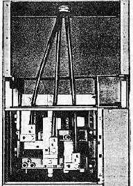
Access to the main lug, main breaker, or main
switch compartment is gained through a hinged
door The top plates (and closing plates In
bottom,
if
present)
are
removable
for
convenience In wiring and cutting conduit
openings.
If the cable is brought into the top of the motor
control center, the cable can be supported at the
point of entry and the top plate by a 5" or smaller
conduit, SQUARE-Duct wireway, or a grommet
centered over terminal L2.
When the entrance of cables is at the bottom
and the cables are required to go to lugs at the
bottom of the section, the incoming line cables
can be supported at the point of entry by a 5" or
smaller conduit centered on the L2 terminal.
Additional wiring space can be gained with the
addition of a pull box THE INCOMING POWER
WIRING
MUST
BE
SUPPORTED
AND
RESTRAINED BY THE CUSTOMER FOR THE
MAXIMUM AVAILABLE FAULT CURRENT
For available fault current of 25,000 amperes
RMS symmetrical or larger, further support can
be added by restraining cables with a tight lacing
of 3" hemp rope or a material of equal strength
(such as cable brace) Begin lacing cables
together as close as possible to lug connection
points in the incoming line compartment and
continue lacing to the conduit entry point The
first and last ties should be anchored securely to
the motor control center frame to prevent
slipping All lacing ties should be spaced for the
maximum
available
fault
current
In
RMS
symmetrical amperes nine inches is required for
25,000 amperes, six inches for 42,000 amperes,
and three inches for 65,000 amperes. Where
more than one main lug compartment is
furnished for required ampacity, refer to Rule 12-
108 of the Canadian Electrical Code to assure
equal division of total current among all incoming
line cables involved.
MAIN LUG COMPARTMENTS
Wire Size
American Wire Gauge
Torque In
or MCM
Pound-Inches
310-200
200
250-400
250
500-750
300
MAIN & BRANCH FEEDERS
Frame
Ampere
Torque in
Size
Rating
Pound-Inches
FA
15-30A
20
35-100A
50
KA
70-225A
250
LA
125-175A
200
200-400A
300
MA
4510DOOA
300
PA
800-2000A
300
Load and Control Wiring
I-15B
The top horizontal wire trough and the vertical
wire trough provide a convenient area to run load
and control wires Openings between sections
permit the wire to pass through from one section
into the next for interwiring.
Because of the intersection of the vertical and
horizontal wire troughs, wires may be routed
without the use of fishtapes. On 7 space factor
construction, where the bottom unit is 3 75" (95
mm) from the floor, a reduced size bottom wire
trough is available for bottom entry of user’s wire
The bottom unit and unit support pan must be
temporarily removed to gain access to this area.
On 6 1/2 space factor construction, where the
bottom unit is 9/2" (241 mm) from the floor, a
bottom cover plate is removed to gain access to
an 8" (203 mm) high wire trough.
Control and load wires are routed to each unit
via wire ports These ports open into the vertical
wire trough permitting control and load wiring to
enter easily After wires are installed, the wires
should be tied down with the wire ties provided in
the vertical wire trough
(Page 3-128)


