TM 5-3895-374-24-2
SECTION II
INSTALLATION
& START UP
2.1. RECEIPT OF EQUIPMENT
Examine all crates and cartons to ensure receipt of
ordered parts. Accessories such as gaskets, discharge
adapter, slow motion switch and the like are listed as
separate items on the packing slip. Register a claim with
the carrier for lost or damaged equipment. Remove and
save all tags and instructions attached to the equipment.
This information is the basis for establishing a proper
maintenance schedule.
2.2. STORAGE
Indoor storage is recommended. If outdoor storage is
required, it is essential that the internal parts of the
feeder be coated with an anti-rust compound and a
weatherproof cover be provided. If long term storage is
required, consult factory.
2.3. INSTALLATION
CAUTION
All
electrical
wiring
must
meet
applicable state and local codes.
Available power must be the same as the electrical
requirements specified on the motor nameplate. A
combination magnetic starter shall be provided to
protect the motor.
This starter shall have a fused disconnect with a lock-out
feature and shall have thermal overloads (heaters)
sized for the full load amperage shown on the motor
nameplate.
-
Before operating the feeder, make sure that no
foreign objects have been left in the Airlock during
installation.
-
Before operating those feeders provided with relief
vents and/or air purge connections, make sure all
applicable piping is in place and that the air purge is
operational.
-
Before operating, check oil level in the speed
reducer. Standard Winsmith reducers are shipped
with oil installed. To prevent oil loss during shipment
there is a brass pin in the filler/vent plug. This pin
must be removed prior to operation or reducer
damage may result.
-
Before operating unit, mechanically disconnect drive
and jog driver. Check to be sure that Roto-Flo unit
will operate in proper rotation. Standard units
operate CW as viewed from drive side unless
otherwise specified on order. Serious damage may
result from reverse operation.
After all electrical and piping connections (where
applicable) are checked, the feeder may be operated for
continuous service.
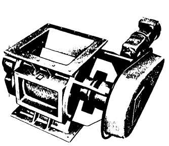
DRIVE PACKAGE ASSEMBLY
page 3 - 727