TM 5-3895-374-24-2
adjusting screw (D). The pump discharge pressure pushes
against the under side of the poppet at point (E). When the
force exerted by the liquid under the poppet exceeds that
exerted by the spring. the poppet lifts and liquid starts to flow
through the valve. As the discharge pressure builds up more
and more of the liquid flows through until a pressure is
reached at which all of the liquid being pumped is going
through the valve This pressure is the relief valve setting.
CAUTION
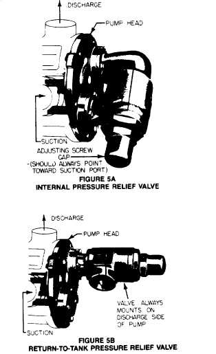
THE INTERNAL TYPE PRESSURE RELIED
CALVE MOUNTED ON THE VIKING PUMP
SHOULD ALWAYS HAVE THE CAP OR
BONNET
POINTED
TOWARD
THE
SUCTION SIDE OF THE PUMP. THE
RETURN-TO-TANK
TYPE
PRESSURE
RELIED VALVE SHOULD ALWAYS BE
MOUNTED ON THE DISCHARGE SIDE OF
THE PUMP. IF PUMP ROTATION IS
PERMANENTLY REVERSD CHANGE THE
RELIEF CALVE. TURN THE INTERNAL
TYPE END FOR END ; MOVE THE
RETURN-TO-TANK TYPE TO THE OTHER
PORT.
IF,
ON
A
PARTICULAR
INSTALLATION
IT
IS
INTENT
TO
REVERSE
THE
PUMP
ROTATION
FREQUENTLY, e.g., USING ONE PUMP
TO FILL A TANK AND THEN BY USE OF A
REVERSING SWITCH OR OTHER MEANS
CHANGING ROTATION TO PERMIT THE
SAME PUMP TO CIRCULATE THE LIQUID
THROUGH A HEATER OR TO LOAD OUT)
THEN OVER PRESSURE PROTECTION
MUST BE PROVIDED FOR BOTH SIDES
OF
THE
PUMP
OR
FOR
BOTH
ROTATIONS.
USE
AN
INTERNAL
PRESSURE RELIEF VALVE TO PROTECT
ONE SIDE AND AN IN-LINE PRESSURE
RELIEF
VALVE
TO
PROTECT
THE
OTHER; USE AN IN-LINE PRESSURE
RELIEF VALVE ON EACH SIDE OF THE
PUMP
OR
USE
SOME
MEANS
OF
LIMITING TORQUE THAT IS FUNCTIONAL
IN BOTH DIRECTIONS OF ROTATION.
Viking pumps can be furnished with either an internal pressure
relief valve - one which directs the flow from the valves back to
the suction side of the pump - or a return-to-tank valve which
directs the flow through piping back to supply tank. See figure
5. An inline pressure relief valve mounted in the discharge
piping also directs the flow back to the supply tank. This type
of valve should be mounted close to the pump so that the
pressure drop though the piping between the pump and the
valve is at the minimum. Be sure there are no shutoff valves
between the pump and relief valve. Piping from a return-to-
tank or an in-line valve to the supply tank should also be as
short and large as possible.
The spring loaded poppet-type valve is strictly a differential
valve, sensing only those pressures on each side of the
poppet. It should not be used as a pressure or flow control
device. It is intended strictly as a pressure relief valve.
The pressure at which either the return-to-tank or internal
pressure relief valve bypasses can be changed by turning the
adjusting screw. Do not back the adjusting screw all the way
out.
NOTE
on some models the pressure relief valve
is mounted on the pump casing instead
of the pump head.
Stop when spring tension is off the screw (the screw starts to
turn easily).
For details on maintenance of the relief valve see Technical
Service Manual covering your model series.
6.
Motor - follow local electrical codes when hooking up
motors.
Foundation
Every pump should have a good foundation. It may be any
structure sufficiently strong to hold the pump rigid and to
absorb any strain or shock that may be encountered.
A certified print of the pumping unit should be used in
preparing the foundation. As for one. If a separate foundation
is provided. make it at least four inches wider and longer than
the base of the unit.
When the unit is placed on the foundation it should be leveled
and checked for position against the piping layout and then
fastened down.
Page 3 - 1203