TM 5-3895-374-24-2
D - Assembly
1.
Slide spacer (266) against shaft shoulder and install
new or cleaned bearing (230) with retaining ring
(260) on shaft.
2.
Press bearing & shaft assembly in bearing housing
(210). Do not over grease. Close bearing cavity with
bearing cover (221).
3.
Install O-ring (81) in pump cover (3) and clamp pump
shaft in vise (use soft claws).
4.
Slide cover assembly over shaft until cover is seated
in bearing housing.
5.
Install key (256), impeller (30), lockwasher (292) and
secure with impeller nut (286).
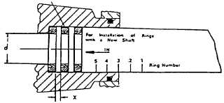
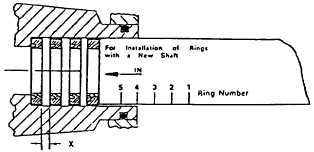
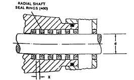
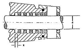
Figure 6
Installing Radial Seal Rings
New Shaft
Figure 6a
Figure 6b
Figure 6c
6.
Install new gasket (80) to sealing face and bolt
assembly to casing (2) with bolts (170). Torque bolts
per table below:
Boll Size
M8
M10
M12
M16
Approx Dia
5/16"
3/8"
1/2"
5/8"
Torque N•m
12
25
40
90
Ft. Lb.
8
20
30
65
7.
Loosen vent plug (130) and fill pump with liquid being
pumped. Tighten vent plug (130) and test pump under
hydrostatic pressure not to exceed 300 PSIG. Refer to
Section III, Paragraph A.
Shaft Dia
’d’
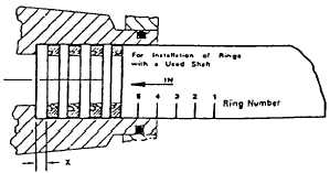
‘X’
25 mm
3 mm
32 mm
4 mm
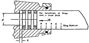
Figure 7
Installing Radial Seal Rings
Used Shaft
Figure 7a
Figure 7b
Figure 7c
page 3 - 1147