TM 5-3895-374-24-2
955-257
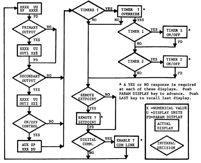
SECTION 7 - FLOW CHARTS
7.1 FLOW CHARTS
The following flow charts are provided to assist you in understanding the sequence of displays available to you. The
rectangular boxes are reproductions of the actual alphanumeric displays. You can follow the flow chart as you push the
appropriate keys on your controller.
For Example: In the TUNE loop, flow chart 7.3, you can scroll through the entire Tune program simply by pushing the
appropriate keys. If you do not change any tuning values, scrolling through the loop will have no effect on the controller.
The CALIBRATION loop, flow chart 7.4, should be used only by those qualified to calibrate the controller.
CAUTION:
DO NOT ENTER THE CALIBRATION LOOP UNLESS QUALIFIED AND EQUIPPED FOR
CALIBRATION.
7.2 THE OPERATOR FLOW CHART
ECLIPSE INSTRUMENTATION DIVISION
(page 3 - 1124)