TM 5-3895-374-24-2
SECTION 6 - CALIBRATION
6.1
CALIBRATION
The controller is delivered from the factory or distributor fully calibrated and ready to use. Recalibration is not normally
required or recommended but it may be necessary in order to meet plant operating standard or to recover from
extraordinary circumstances such as the DATA LOST/PLEASE CAL mode.
The term CALIBRATION in this controller includes both a CONFIGURATION procedure and a REFERENCE procedure.
The CONFIGURATION procedure refers to those steps that must be performed to tell the microprocessor details of the
application including input, output, control action, alarm, display units, span and time base. These details are to be keyed
through the front keypad in a structured sequence. The REFERENCE procedure is the more traditional calibration
using an external reference source. A structured program also exists for this calibration. A calibration loop flow chart in
Section 7.4 is available to help explain the controller calibration.
Controller calibration can be performed at the normal controller installation or on a bench. Only AC power and an
appropriate input are necessary. If an input is not convenient, a jumper between Terminals F and H is adequate for
CONFIGURATION calibration. REFERENCE calibration requires a precise calibration source for the input signal. Be sure
to cover AC power terminals.
CAUTION:
COMPUTER DEVICES ARE NON-FORGIVING. KEY SEQUENCES AND INSTRUCTIONS
MUST BE FOLLOWED PRECISELY. DO NOT SKIP ANY STEP. DO HOT TURN OFF
POWER WHILE IN CAL LOOP.
6.2
ENTERING CALIBRATION PROGRAM
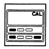
A security code protects the calibration procedure. To
enter the calibration mode push the three keys as
indicated in Figure 6-1 simultaneously. A front key pad
"CAL" will illuminate. If it does not, push the RETURN
key and then push the 3 key code again.
FIGURE 6-1
6.3
PART NUMBER
PN XX XX
XX XX XX
The PART NUMBER is the first CAL loop display. If this display does not appear, push the
LAST key until it is on the display. This 10 digit PART NUMBER fully defines the controller.
This controller has been manufactured with specific hardware that determines its input and output capability. The PART
NUMBER defines this capability. The PART NUMBER also defines some items that can be changed by a keypad
instruction without any hardware change. For example: In a controller provided with thermocouple input, the type of
thermocouple can be changed by a keypad instruction. However an input cannot be changed to an RTD or process input
unless a hardware change is also made. CONFIGURATION calibration deals specifically with those items that can be
changed strictly by a keypad instruction.
ECLIPSE INSTRUMENTATION DIVISION
page 3-1117