TM 5-3895-374-24-2
ACCESSORIES
Fireye P/N
Description
For More Information
E300
Expansion Module
See Bulletin E3001
ED150
Remote reset cables
See Bulletin E8001
ED550
Remote display cables
See Bulletin E8001
ED400
Remote display mounting kit
See Bulletin E8001
ED600
Multiple Cable Adapter
See Bulletin E8001
E500
Communication Interface
See Bulletin E5001
E700
Software Program to Monitor
E500 Operation IBM Compatible
See Bulletin E7001
E900
Service Tool
See Bulletin E9001
60-2333
Noise Line Filter
See Bulletin E1021
OPERATION
The Fireye FLAME-MONITOR provides the operator with a constant status read-out as well as
diagnostic information. It has 42 messages which are simple to understand and interpret.
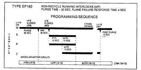
For purposes of illustration, we will be looking at the EP160 Programmer functions and messages in
this bulletin. Because the messages change depending upon which programmer is being used, it
is necessary to check the bulletin covering the specific programmer for exact details.
Note: PTFI - Pilot trial for ignition
MTFI - Main burner trial for ignition
CAUTION: On initial power-up and on restarts following a power failure, the display on the con-
trol will not become active for 15 seconds when using a Programmer having a date code followed
by a number greater than 11. (i.e. date code 8740-12)
Refer to the suggestions shown in this bulletin before proceeding to power the Fireye FLAME-MONI-
TOR system. Items such as scanner installation, short circuit tests and safety information should be
reviewed.
Start-Up (Normal Cycle)
Note: For direct spark ignited oil burners, substitute the words Main-oil Valve for Pilot Valve.
1.
Constant 120 VAC should be available to the LI-L2 terminals only on the wiring base.
2.
The operating control circuits (L1-13) will close, signaling the burner to start its firing sequence.
3.
Assuming the fuel valve end switch (13-3) is closed, the burner/blower motor (terminal M) circuit
is energized. The running interlock (limit) circuit (3-P) will close (eg: all limits, interlocks, etc.
are proven).
4.
The firing rate motor (Modulator Motor) is driven toward the high purge open damper position
(10-X ckt. made).
FLAME SAFEGUARD
(page 3 - 1044)