TM 5-3895-374-24-2
Figure 28
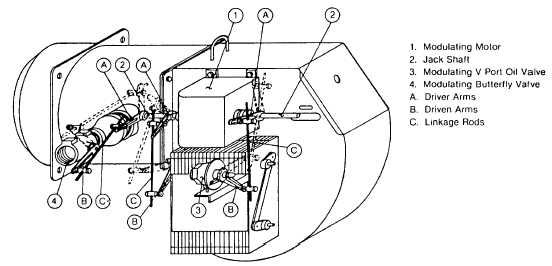
Gas/Oil Linkage Adjustment For Full Modulation Standard System
Typical general linkage arrangement for combination gas/oil full
modulation burner, shown in low fire light off position. Dotted lines
indicate
approximately
high
fire
position.
When
making
adjustments, make certain the motor can make its full 90 stroke
without any linkage binding.
Driver Arms (A) connected to the Modulating Motor (1) Jack Shaft
(2) will increase the travel of the Driven Arms (B) as the Linkage
Rod (C) ball joint is moved away from the Jack Shaft. The travel of
the Driven Arms will be increased as the Linkage Rod ball joint is
moved toward the shaft of the driven device.
4. GENERAL START UP PROCEDURES-ALL FUELS
All Fuels · General Start Up
A thoroughly qualified burner technician should be employed to
provide the initial burner start up, as well as any subsequent
servicing.
A representative of the owner and/or the person or persons
responsible for operating and maintaining the unit should be
present during the initial start up.
A service representative may also be required by the local utility on
gas fired equipment. Instructions regarding the proper care and
maintenance of the unit should be outlined with these people
present.
Before beginning start up, the start up technician should
thoroughly study and become completely familiar with the exact
sequence of operation and all other details of the specific flame
safeguard control system being used. This information will be
found in bulletins printed and supplied by Honeywell or Electronics
Corporation of America (Fireye). A copy of this bulletin was
supplied with the burner.
After the burner is mounted and all wiring and piping has been
completed, tested and determined to be correct, the following
procedures are recommended:
For combination gas/oil units; the gas side operation should be set
up first to “clock the gas meter”, allowing precise gas inputs to be
determined. Once the gas operation is complete, the oil side can
be set up easily by correlating the CO2 values of the two fuels.
See page 36, Table 13, “CO2-O2 Ratio Curves for Fuel Oils and
Gases.”
If it is anticipated that the Gas/Oil burner will rarely run on oil; it is
recommended that the blower motor driven oil
pump drive coupling be removed - and replaced only when
required for oil firing. If, however, the pump coupling is left
connected to the blower motor, it is essential to ensure that the
pump has a good oil supply, when the burner is operating on the
gas cycle, so that it will not run dry. Be certain on initial start up
that the pump is adequately primed to prevent against mechanical
seizure caused by lack of oil. The pump warranty will be voided if
the pump is run without adequate oil supply.
1.
Make a general inspection tour of the equipment room to
ensure that the installation is complete. Check piping,
controls, wiring and etc.
2.
Close main and checking gas cocks. Open suction line
manual oil valves and others as appropriate.
3.
Tighten all screws on terminal blocks in control cabinet in
case some may have loosened in shipment.
4.
Do not secure flame safeguard control into its wiring
base until it has been determined that there are no shorts
or grounds in the system.
5.
Check fuses in main panel and in burner control cabinet.
Check wiring to the burner control cabinet for compliance
with the wiring diagram and local codes. Determine that
voltage supply is correct to motor starter line connections
and to control circuit line connections. If a control circuit
transformer is supplied, make certain its primary voltage
matches the line voltage being supplied. (A 230 volt
transformer does not produce proper control voltage
when supplied with 208 volts.)
(page 3 - 973)