TM 5-3895-374-24-2
the Air Dampers is controlled by positioning the Air Damper Drive
Arm (13) relative to the Acorn Nut (16) mounted on the end of the
Hydraulic Cylinder (9) piston rod. The maximum travel is with the
Damper Drive Arm positioned to be in contact with the hydraulic oil
cylinder Acorn Nut at all times. If less travel is desired, set the Air
Damper Drive Arm to allow a gap between it and the Acorn Nut.
(Depending on Air Damper positioning, it may be necessary to
loosen its set screws to attain proper Air Damper opening
distance.) The wider the gap (when the burner is off), the less the
overall travel when going to high
fire position. When setting the Drive Arm position relative to the
Acorn Nut, make certain that the Air Damper travel is correct for
proper combustion at all firing positions and that there is no
binding of the Linkage or Dampers. Maker certain the cast iron
Linkage Return Weight (15) is secure on its Linkage Arm (17).
*Not shown in this depiction. See page 4, Fig. 2.
Note 1
Component operational
sequencing
will
vary with the specific Flame Safeguard
Control being used Refer to the specific
Flame Safeguard Control bulletin supplied
with the burner for complete information.
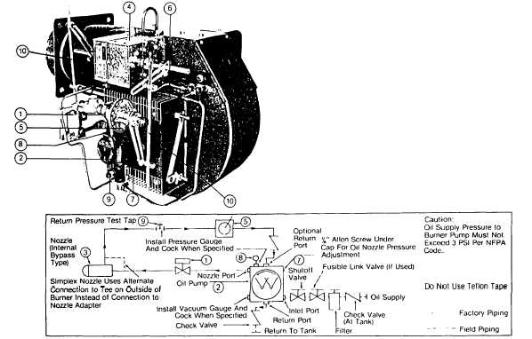
Figure 25
Typical Oil Burner with Full Modulation Fuel/Air Control
MECHANICAL OPERATION: The Full Modulation system uses a
two-stage Oil Pump (2) with an internal bypass type Oil Nozzle
(See page 20, note 1). A Modulating Motor (4) controls the
positioning of the Air Dampers (6) and the Modulating Oil Valve (5)
in the nozzle return line through mechanical linkage. A direct
spark oil ignition system will normally be supplied at firing rates up
to 45 GPH. Above that rate burners will be supplied with a spark
ignited gas pilot’ to light the main oil flame. Certain insurance
company codes will require the gas pilot system on all input sizes.
At main flame light off the normally closed Oil Valve (1) is
energized, allowing oil to flow to the Nozzle. The Modulating Oil
Valve is adjusted to allow a controlled amount of oil to bypass the
Nozzle, which keeps the pressure reduced to the nozzle for low
fire light off. Nozzle oil supply pressure is set by adjusting the Oil
Pump pressure regulating 1/8” Allen wrench fitting (7). Turn
clockwise to increase the pressure and counterclockwise to
decrease the pressure to the nozzle. The low fire nozzle
pressures should be taken at the plugged
Oil Pump Gauge Port (8) and should be approximately 300 PSI
(but could be as low as 240 PSI on certain inputs of the C4 and C5
models) with pressure at the Nozzle Bypass Gauge Port (9) from
60 to 100 PSI, these pressures varying with nozzle size and job
conditions. A typical low fire oil flow setting on the Modulating Oil
Valve would be number 7, but will vary with job conditions. After a
brief period of time for the low fire flame to stabilize, the
Modulating Motor will drive the Fuel/Air Linkage (10) to the high
fire position. At this point the Air Dampers will be full open (or as
required for good combustion) and the Modulating Oil Valve will be
at the “closed” position and the nozzle bypass line will be fully
closed, putting full oil pressure to the Nozzle. The Oil Pump
pressure Gauge Port pressure reading will show approximately
300 PSI and pressures at the bypass pressure gauge port will be
180 to 225 PSI, although this will vary with the specific nozzle size
being used. Refer to page 30, Table 8 to determine specific nozzle
pressures and firing rates. A modulating
(page 3 - 971)