TM 5-3895-374-24-2
6-2 Mounting of trolley onto beam
(1) Adjustment of trolley width before mounting onto beam.
Adjust the trolley width for the following proper clearance.
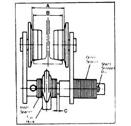
Adjustment of "A" dimension:
Proper "A" dimension when both side plates are spread fully out-
side is as follows:
PT or GT : Beam width (B) + approx. 4mm
Make adjustment by adding or taking out the outer spacers,
without caring about the number of spacers shown in Table 2.
Adjustment of C dimension:
Proper C dimension is approx 7-13mm. Make adjustments by
adding or taking out the inner spacers on side-plate S side,
without caring about the number of spacers shown in Table 2.
There is a difference of spacer between the right and left
side. However, this does not pose any problem. Minimum
one piece of spacer is required on both sides.
After trolley width adjustment, insert a split pin into the
stopper pin, bend it temporarily to an extent that it does not
come off.
Fig. 5
(2) In case the trolley is put onto the beam flange from the open
end of the beam as it is connected to the hoist.
1) Bend the temporarily bent split pin for the stopper pin surely.
2) Remove the stopper at the end of the beam, and put the trolley
(page 3 - 884)