NOTE
Ideal ambient temperature is (70F) 21C).
In cold climates, it is desirable to install the
compressor within a heated building. Choose a clean,
relatively cool location, and provide ample space around the
unit for cooling and general accessibility. Place the beltwheel
side toward the wall, leaving at least 15" (380mm) for air
circulation to the beltwheel fan. The location should also be
near a source of water and a drain line to simplify piping
connections if a water-cooled aftercooler is to be used. (Note:
If a detached receiver is to be used, consider placing the
receiver outdoors to provide more effective heat dissipation,
keeping in mind that condensed water in the receiver may
freeze).
Provide adequate fresh air and exhaust ventilation
from area in which the compressor is located. Provide 1,000
cu. ft. fresh air per minute per 5 horsepower. Ventilation by
gravity or mechanical means is approved.
INLET PIPING
If the air in the vicinity of the compressor is unduly
dirty or contains corrosive fumes, we recommend piping the air
filter/ silencer to a source of cleaner air or use an
optional
heavy duty filter.
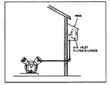
If it is found necessary to install inlet
piping, make the line as short and direct as possible and as
large, or larger than the diameter of the inlet connection at the
compressor. The inlet piping must increase in diameter for
every 50’ (15.25m) of length. If the total length is between 50’
(15.25m) and 100’ (30.5m). increase the pipe diameter at the
mid-point in the length, i.e., if the total length is 80’ (24.4m),
increase the pipe diameter at the 40’ (12.2m) point. Attach the
air cleaner to the end of the inlet air line, and if the inlet is
piped outdoors, it should be hooded to prevent the entrance of
rain or snow. See Figure 2-1. Fine airborne dust, such as
cement and rock dust, require special filtration equipment not
furnished as standard equipment on this compressor. Such
filtration equipment is available from your local Ingersoll-Rand
Distributor.
Figure 2-1. Inlet piping arrangement.
A well ventilated location should be selected for this
machine when operating in very damp climates or under
conditions of
high humidity.
These atmospheric conditions
are conducive to the formation of water in the crankcase, and
if adequate operation and ventilation are not provided, rusting,
oil sludging and rapid wear of running parts will result. This is
particularly true when operating on very intermittent duty
applications.
The unit may be bolted to any substantial, relatively level floor
or base. If such a surface is not available. an adequate base
must
be constructed. Should a concrete base be necessary, make
certain the foundation bolts are positioned correctly to accept
the receiver feet, and that these bolts project at least 1" (25.4
mm) above the surface of the foundation.
The unit must be levelled and bolted in a manner
which avoids pre-stressing the receiver in order to prevent
vibration and insure proper operation. The following technique
is recommended for anchoring this unit:
A.
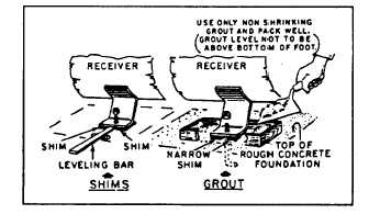
Tighten evenly, and to a moderate torque, the nuts of
any three of the four receiver feet. Check the unit for
level. If the unit is not level, insert metal shims, as
shown in Figure 2-2, under one or two of the feet to
obtain level, and retighten the nuts.
B.
Note the distance the unanchored foot is elevated
above the base and insert a metal shim of equal
thickness under this foot to provide firm support.
Shims must be at minimum the same dimension as
bottom of foot.
C.
After all shims are inserted and the unit is level, pull
up the nuts on all receiver feet to a moderate (not
excessively tight) torque.
D.
Check for receiver stress by loosing nuts (one at a
time), and note any upward movement of the
mounting foot. Any noticeable movement indicates
that step B must be repeated.
Figure 2-2. Methods of Leveling Unit.
Severe vibration will result when nuts are pulled down
tightly and feet are not level.
This
can
lead
to
welds
cracking or fatigue failure of receiver. This is a very important
part of installation.
THE COMPRESSOR SHOULD NEVER BE
OPERATED WHILE MOUNTED TO THE
SHIPPING CRATE SKID
Step.
5
ELECTRICAL
(See electrical diagrams on Page 24).
To avoid invalidating your fire insurance, it is
advisable to have the electrical work done by a licensed
electrician who is familiar with the regulations of the National
Electrical Code and the requirements of the local code.
Sizes of copper wire to use for distances up to 50 feet
(15.3m) from the feeder-60 Hertz.
MOTOR
THREE PHASE
HORSEPOWER
200v
230V
400V
575V
AWG-(75C)
AWG-(75C)
AWG-(75C)
AWG-(75c)
10
8
8
12
14
15
4
6
8
10
20
3
4
8
10
25
1
2
6
8
30
0
1
6
8
page 3 - 831
TM 5-3895-374-24-2
Sizes of copper wire to use for distances up to 50 feet
15.3 m) from the feeder-60 Hertz.
MOTOR
THREE PHASE
HORSEPOWER
200v
230V
400V
575V
AWG-(75C)
AWG-(75C)
AWG-(75C)
AWG-(75c)
10
4
6
10
10
15
3
4
8
10
20
1
2
6
8
25
0
1
6
8