TM 5-3895-374-24-2
OPERATING CHARACTERISTICS
Roots UNIVERSAL RAI® blowers, as covered in
this manual. are designated as air blowers, and may
be used for handling air in either pressure or vacuum
service. They are unsuitable for handling gases
because shaft seals are not designed to prevent
leakage to atmosphere.
The
Roots
rotary
lobe
blower
is
a
positive
displacement type unit. whose pumping capacity is
determined by size. operating speed and pressure
conditions. It employs two double-lobe impellers mounted
on parallel shafts and rotating in opposite directions within
a cylinder closed at the ends by headplates. As the
impellers rotate. air is drawn into one side of the cylinder
and forced out the opposite side against the existing
pressures.
The
differential
pressure
developed.
therefore, depends on the resistance of the connected
systems.
Effective sealing of the blower inlet area from the
discharge area is accomplished by use of very small
operating clearances. Resulting absence of moving
contacts eliminates the need for any internal lubrication.
Clearances between the impellers during rotation are
maintained by a pair of accurately machined timing gears,
mounted on the two shafts extending outside the air
chamber.
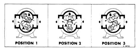
Operation of the familiar basic rotary lobe blower is
illustrated in FIGURE 1. where air flow is right to left from
inlet to discharge with the bottom impeller rotating
clockwise. In Position 1 it is delivering a known volume
(A) to the discharge, while space (B) between the upper
impeller
and
cylinder
wall
is
being
filled.
Counterclockwise rotation of this impeller then traps equal
volume (B) in Position 2. and further rotation delivers it to
the discharge in Position 3. At the same time. another
similar volume is forming under the lower impeller, and
will be discharged when rotation reaches Position 1 again.
One
complete
revolution
of
the
driving
shaft
alternately traps four equal and known volumes of air (two
by each impeller and pushes them through to the
discharge, the pumping capacity of a lobe blower
operating at a constant speed therefore remains relatively
independent of reasonable inlet or discharge pressure
variations. To change capacity, it is necessary either to
change speed of rotation or vent some of the air.
No attempt should ever be made to control capacity
by means of a throttle valve in the intake or discharge
piping. This increases the power load on the driver. and
may seriously damage the blower. Likewise. if a
possibility exists that flow to the blower inlet may be cut off
during normal operation of a process, then an adequate
vacuum relief valve must be installed near the blower. A
pressure type relief valve in the discharge line near the
blower is also strongly recommended for protection
against cut-off or blocking in this line.
When a belt drive is employed. blower speed can
usually be adjusted to obtain desired capacity by changing
the diameter of one or both sheaves. See pages 18 and
20 for minimum sheave diameter. In a direct coupled
arrangement. a variable speed motor or transmission is
required, or air may be vented through a manually
controlled unloading valve and silencer. If discharge air is
returned to the blower inlet, it must be cooled to 100F
(38C) through a cooling by-pass arrangement.
Before making any change in blower capacity or
operating conditions, contact the nearest Distributor for
specific information applying to your particular blower.
In all cases. operating conditions must be maintained
within the approved range of pressures. temperatures
and speeds as stated under LIMITATIONS. Also. the
blower must not be used to handle air containing liquids or
solids, or serious damage to the rotating parts will result.
OPERATING LIMITATIONS
To permit continued satisfactory performance, a
Roots UNIVERSAL RAI® blower must be operated
within certain approved limiting conditions. The
Manufacturer's warranty is, of course, also contingent
on such operation.
Maximum limits for pressure, temperature and
speed are specified in Table 1 for various sizes of
UNIVERSAL RAI® blowers. These limits apply to all
blowers of normal construction, having operating
clearances as listed in Table 5 when operated under
standard atmospheric conditions. Do not exceed any
of these limits.
Example: The listed maximum allowable temperature
rise increase in air temperature between inlet and
discharge) for any particular blower may occur well before
its maximum pressure or vacuum rating is reached. This
can easily occur at high altitude or at very low speed.
Figure 1-Flow Through a Basic Type RAI Blower.
page 3-801