page 3 - 741
TM 5-3895-374-24-2
A 122-92
VI.
Gap Adjustment
A.
Check switch for proper mounting (see Fig. 1 A & 1 B)
B.
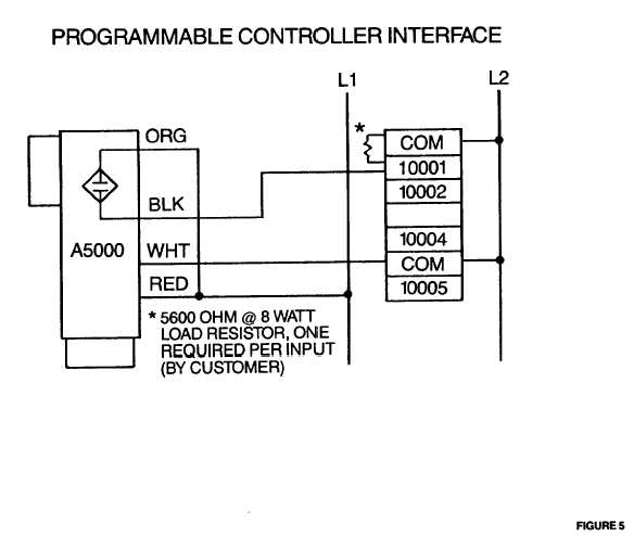
Check switch for proper wiring connections (see Fig. 3)
C.
Remove back cover switch (CAUTION: 115VAC). Locate LED light mounted on circuit board
D.
With machine operating and shaft rotating, check LED for flashing light
1.
Move switch toward magnet disc until light begins to flash
2.
If LED light does not flash:
a.
Check alignment
b.
Move switch closer to magnet disc
c.
Check switch wiring
d.
Check power source
e.
Consult factory

