TM 5-3895-374-24-1
GP470FA
Usings terminals SP and +5v will result in the output signal being
normally LO (0v) and going HI (+5V) when setpoint weight is reached. This
output will sink 20 ma, suitable for driving a solid state relay (CRYDOM
TD120 or equivalent). See Section II Operation for a description on how to
operate the setpoint feature.
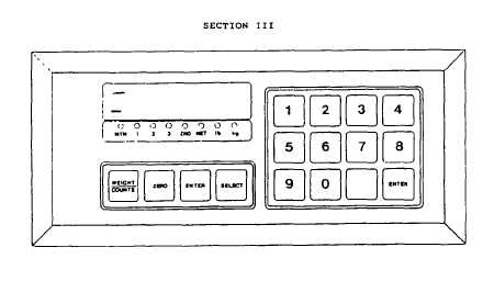
FIG. 5 - KEYBOARD WHILE IN CALIBRATION MODE
SECTION III - CALIBRATION
How to Enter the Calibration Mode
The Calibration Mode is accessed by pressing the Channel number
(1,2, or 3) and the Calibration key [9]. For example:
To calibrate Channel 1 press [1] [9] {SELECT] accessed
To calibrate Channel 2, press [2] [9] [SELECT]
To calibrate Channel 3. press [3] [9] [SELECT]
The display will now flash ‘Press’, asking you to press the pushbutton
accessed through the small hole at the back of the indicator.
You must press this button within 30 seconds of selecting Calibration
Mode. If the button is not depressed in time, the indicator will return to the
previous display and you must repeat the above procedure.
When the Calibration Mode has been enabled, a flashing 'I' will
appear in the far left display digit.
NOTE:
In Calibration Mode the keypad is different as most of the
keys change their function. Please refer to the illustration
on the opposite page to familiarize yourself with the key
functions.
Note especially the following
[ON/OFF] becomes [WEIGHTS/COUNTS] to select between display
of scale weight or internal counts. A flashing 'A' in' the
leftmost digit indicates internal counts displayed.
[TARE]
becomes [ENTER] to allow entry of any change in
parameters and calibration values.
Set-Up Parameters
In order to calibrate the indicator, certain parameters mist be set up first
before weights are applied on the scale. The indicator should first be set up
for graduation size, overweight, motion window, push to zero range, etc. The
reason for this is, if the dead load is set or the span is calibrated and one of
the indicated parameters is changed afterwards, the span or the dead load
might change as well.
(page 3- 62)