TM 5-3895-374-24-1
GP470FA
G. OPERATION
DC200E CONTROLLER
The Honeywell DC200E controller has been configured at the factory with parameters which generally produce accurate
pressure control. Before making any field adjustments, other then as noted in this instruction sheet, PLEASE CONTACT
THE HAUCK SERVICE DEPARTMENT.
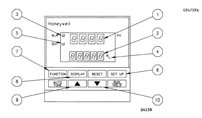
Figure 4 shows the front face of the DC200E instrument. Following figure 4 are functional descriptions of the displays and
keys.
Fig. 4
1.
Upper Display: Normally displays drum suction in inches of water. Setpoint (SP or 2SP), deviation (DEV) and
output (OUT) values may be shown on demand. Parameter values are displayed when in the configuration setup
mode.
2.
Lower Display: Displays function groups and operator prompt when in the configuration setup mode. Also
displays SP, PV, DEV, and OUT parameter prompts when the DISPLAY key is pressed.
3.
ALM 1: Illuminated when alarm 1 setting has been exceeded. Alarm 1 is normally not configured for aggregate
drying applications.
4.
R: Illuminated when the remote setpoint or second local setpoint has been selected.
(page 3-38)