TM 5-3895-374-24-1
Sure-Flex Installation Instructions (continued)
Different coupling sleeves require different degrees of alignment precision. Locate the alignment values for your sleeve
size and type in Table 2 below.
5.
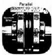
Check parallel alignment by placing a straightedge across the two coupling
flanges and measuring the maximum offset at various points around the
periphery of the coupling without rotating the coupling. If the maximum offset
exceeds the figure shown under "Parallel" in Table 2, realign the shafts.
6.
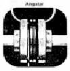
Check angular alignment with a micrometer or caliper. Measure from the
outside of one flange to the outside of the other at intervals around the periphery
of the coupling. Determine the maximum and minimum dimensions without
rotating the coupling. The difference between the maximum and minimum must
not exceed the figure given under "Angular" in Table 2. If a correction Is
necessary, be sure to recheck the parallel alignment.
TABLE 2 - MAXIMUM RPM AND ALLOWABLE MISALIGNMENT
(Dimensions in inches)
Sleeve
Maximum
Types JE. JN. JES JNS, E & N
Type H & HS
Size
RPM
Parallel
Angular
G1
Parallel
Angular
G1
3
9200
.010
.035
1.188
4
7600
.010
.043
1.500
5
7600
.015
.056
1.938
6
6000
.015
.070
2.375(1)
.010
.016
2.375
7
5250
.020
.081
2.563
.012
.020
2.563
8
4500
.020
.094
2.938
.015
.025
2.938
9
3750
.025
.109
3.500
.017
.028
3.500
10
3600
.025
.128
4.063
.020
.032
4.063
11
3600
.032
.151
4.875
.022
.037
4.875
12
2800
.032
.175
5.688
.025
.042
5.688
13
2400
.040
.195
6.625
.030
.050
6.625
14
2200
.045
.242
7.750
.035
.060
7.750
16
1500
.062
.330
10.250
.
Note.
Values shown above apply if the actual torque transmitted is more than 1/4 the coupling rating For lesser torque,
reduce the above values by 1/2.
* Type H and HS sleeves should not be used as direct replacements for EPDM or Neoprene sleeves
(1) Value when using 6J flanges is 2 125
7.
If the coupling employs the two-piece sleeve with the wire ring, force the ring into its groove In the center of the sleeve.
It may be necessary to pry the ring Into position with a blunt screwdriver.
8.
Install coupling guards per OSHA requirements.
CAUTION:
Coupling sleeves may be thrown from the coupling assembly with substantial force when the coupling Is
subjected to a severe shock load or abuse.
T. B. WOOD'S SONS COMPANY • Chambersburg, PA 17201
T. B. WOOD'S CANADA LTD. • Stratford, Ontario N5A 6V6
FORM 741E 5-92
Printed In U.S.A.
(page 3- 622)