TM 5-3895-374-24-1
Sure - Grip
Sheave- Bushings
Installation Instructions
Before beginning installation, identify the bushing as follows: Sizes JA through SK manufactured from “Sinstell” All but
Size JA have provision for a setscrew over the keyway. IMPORTANT Wedging the bushing to spread it during placement
on the shaft could damage the bushing. DO NOT wedge these bushings. Sizes SH through SK manufactured from steel
do not have a keyway setscrew. Sizes SF through S are made from cast iron or ductile iron.
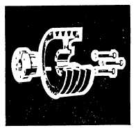
The Sure-Grip tapered OD-type interchangeable bushing offers flexible and
easy installation while providing exceptional holding power. To ensure that
the bushing performs as specified, it must be installed properly.
To Install:
IMPORTANT: DO NOT USE LUBRICANTS IN THIS INSTALLATION
1 Thoroughly Inspect the bore of the mating part and
the tapered surface of the bushing. Any paint, dirt. oil,
or grease MUST be removed.
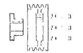
Fig 1 Standard Mounting
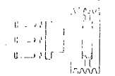
Fig. 2 Reverse Mounting
2 If following the STANDARD MOUNTING procedure
and placing the bushing flange toward the motor,
place the bushing on the shaft, see Fig 1, bushings
NOT made of Sinsteel may require slight wedging
to slip on the shall. To wedge them, insert a
screwdriver into the sawcut through the flange of
the bushing. DO NOT wedge Sinsleel bushings, as
this may damage them. Place the bushing and its
key on the shaft and position them for correct axial
alignment of the drive. Place the mating part on the
bushing, aligning the drilled holes in the part with
the threaded holes in the bushing On M through S
bushings, the mating part and bushing MUST be
assembled so the two threaded holes in the mating
part are located as far as possible from the sawcut
In the bushing Insert the cap screws through the
mating part hub into the bushing flange and finger-
tighten them.
3 If following the REVERSE MOUNTING
procedure, assemble the bushing loosely
into the mating part and insert cap screws
through the drilled holes in the mating part
and thread them into the bushing, see Fig.
2.Place the assembly and its key on the
shaft. Bushings NOT made of Sinsteel
may require slight wedging to allow a slip
fit into position. To wedge, insert a
screwdriver into the sawcut in the bushing
flange.
DO
NOT
wedge
Sinsteel
bushings, as this may damage them.
Position the assembly for axial alignment
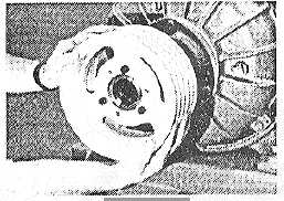
Fig. 3
4 Will the drive properly aligned. tighten all cap
screws evenly and progressively in rotation to
the torque values listed in the table below
When the screws are tighten properly, the
listed torque value will remain on all cap
screws and there will be a slight group
between the flange of the bushing and the
lace of the mating hub. DO NOT attempt to
tighten enough to close this gap. Recheck
drive alignment. If the bushings have
setscrews over the keyways, insert and
tighten them.
(page 3-593)