TM 5-3895-374-24-1
GP255FH
1.
Mount the blower on any level concrete floor or pad. The location chosen must provide an unobstructed flow of air to
the blower inlet If the blower Is Installed on a floor on which other machinery is mounted, install vibration Isolation
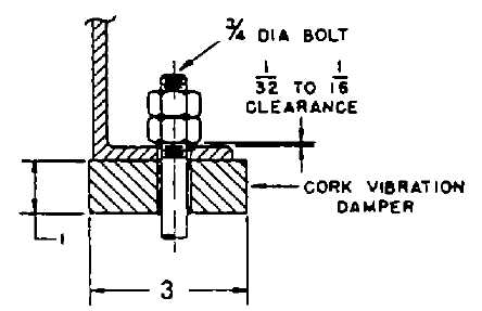
pads between the blower base and the floor. In addition, the mounting bolts must be Isolated from the blower base.
This configuration Is shown in figure 2 Cork isolation pads are available from Hauck.
Fig. 2 Illustration depicting the proper placement of the vibration isolation pad.
If the blower is installed on a structure above the floor, the mass and rigidity of the structure must be such that its
natural frequency is well above the motor or impeller operating frequency to prevent resonance.
2.
Ensure that the piping between the blower and the load has been selected to minimize pressure losses. The
pressure drop for the control valve should be selected for the designed control quality, ranging from 5-30% of the
system drop It is suggested that, where practical, the piping, valves, fittings, etc. be sized for a total pressure drop of
no more than 3.4" water column (2 oz ) 3. Rotate the blower air outlet, as required, to align it with the air piping.
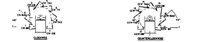
Each blower Is constructed to allow the Impeller to rotate In only one direction Two types of blowers are
manufactured; one provides for clockwise rotation, the other counterclockwise rotation The discharge outlet on each
of these types can be rotated to any one of the seven positions shown below.
Fig 3 - Standard Discharge Positions viewed from motor drive ends.
To rotate the casing, accomplish the following. Do not disassemble the two casing halves.
A
Loosen and remove the eight bolts holding the casing to the base assembly
B.
Rotate the casing as required and reseat the casing against the base assembly.
C.
Ensure that all bolt holes are aligned.
D.
Reinsert and securely tighten all eight bolts.
4.
Connect the air piping to the blower outlet using the rubber sleeve and clamps supplied with each blower Ensure that
the air piping Is completely supported by external hangers to prevent unnecessary strain on the blower casing. In addition
to preventing vibration transfer to the blower, the rubber sleeve prevents the induction of loads In the casing due to
misalignments between the piping system and the blower discharge connection.
(page 3-540)