TM 5-3895-374-24-1
GP440FG
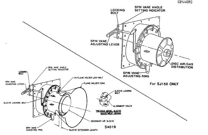
Fig.16 - Schematic representation of the Secondary Air
Sleeve adjustment and Spin Vane Adjusting Ring
P. FLAME HOLDER CONE ADJUSTMENT
The Flame Holder Cone assists in the stabilization of the StarJet’s flame. Nominally, the cone should be positioned so that
it is approximately midpoint in the adjustment range. The cone should also be set square with the burner to adjust the
position of the Flame Holder Cone. To adjust the cone:
1.
Loosen the four Flame Holder Locking Bolts.
2.
Position the Flame Holder Cone. Nominal position is midpoint in the adjustment range.
3.
Place a straight edge horizontally across the Flame Holder Cone.
4.
Measure the distance from the straight edge to the front of the burner on both the left and right sides. Adjust the
cone to get the same measurement on both sides.
5.
Tighten the Flame Holder Locking Bolt on both the left and right sides.
6.
Place the straight edge vertically on the Flame Holder Cone.
7.
Adjust the cone to get the same measurement on both the top and the bottom.
8.
Tighten the Flame Holder Locking Bolt on the top and bottom.
(page 3-523)