TM 5-3895-374-24-1
WALL MOUNTING INFORMATION
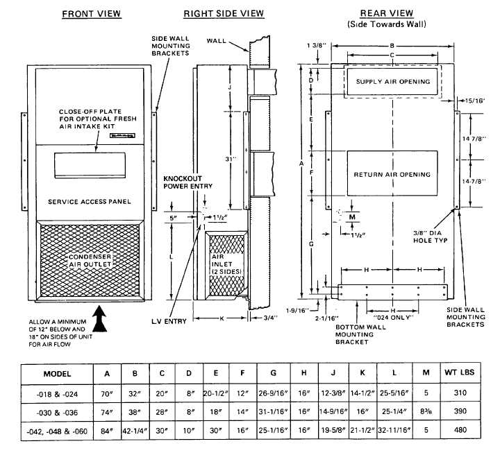
These units are secured by wall mounting brackets
which fasten the unit to the outside wall surface at both
sides and at the bottom
Two holes, the sizes of the supply and return air
openings, must be cut through the wall (see table below)
Allow at least 1/4" additional clearance around the return
air opening
After the wall opening positions have been selected from
the table below, layout the position of the bottom wall
bracket and fasten It to the wall security
Mount the side brackets to the unit prior to installing It
Use only the holes provided in the sides of the unit
housing DO NOT DRILL ANY ADDITIONAL HOLES
On WOOD-FRAME walls, the wall construction must be
strong and rigid enough to carry the weight of the unit
without transmitting any unit vibration (Refer to Page 5
for installation procedure)
CONCRETE BLOCK walls must be thoroughly inspected
to insure that they are capable of carrying the weight of
the Installed unit (Refer to Page 6 for installation
procedure)
(page 3-486)