TM 5-3895-374-24-1’
Chapter 9
Troubleshooting
Identifying 5/02 Processor Communication Errors
The Following
Probable Cause
Recommended Action
Error Exists
1.
Check communication parameters of programmer
Programmer and processor baud rate must match
Programmer and processor node addresses must be
DH485
different
communication
2.
Try different combinations of
parameters are
a. baud rate (Processor default is 19200)
Improperly set up
b. node address (Processor default is 1 )
The 5/02
3.
Try to increase the maximum node address (Default
processor is not
is 31 )
receiving data
1.
Check cable continuity
communication
Bad Connection of
2.
Check cable connections between programmer and
to the
Communication
processor
programmer
Device
3.
Check communication device (for example, the
1747-PIC) Replace if necessary
1.
Verify proper power supply selection and backplane
Low or No Power
loading (1747-PIC and 1747-AC draw power off
to Communication
the backplane)
Device
2.
Verify proper 120/240V power supply jumper
selection See page 5-5.
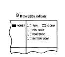
Refer to the following key to determine the status
of the LED indicators
Indicates the LED is OFF
Indicates the LED is ON
Indicates the LED Is FLASHING.
Status of LED does not matter
The RUN LED on the 5/01 processor is actually
labeled "PC RUN ’ Also, the 5/01 processor
does not have a COMM LED.
(page 3-442)