TM 5-3895-374-24-1
Chapter 5
Installing Your Hardware
Components
Installing Your Chassis
Two cables are available to link modular hardware chassis. Catalog Number
Interconnect Cable
1746-C7 cable is 152.4 mm (6 in ) in length and used when connecting chassis
side-by-side. Catalog Number 1746-C9 is a longer cable used to link one
chassis below the other
ATTENTION: Do not use any other cables than those provided
Longer cables could affect the integrity of data communications
between the chassis, possibly causing unsafe operation. Also, make
sure the cable is properly secured to protect against the effects of
shock and vibration.
Install the chassis interconnect cable before Installing the power supply in
multiple chassis configurations.
The cables are "keyed" for proper installation. The end of the cable that plugs
into the right socket in the chassis has the "key" on the top of the connector.
The opposite end of the cable has the "key" on the inside of the connector for
insertion into the expansion chassis.
To remove the cable, move the tabs on the socket outward and connector will
pop out.
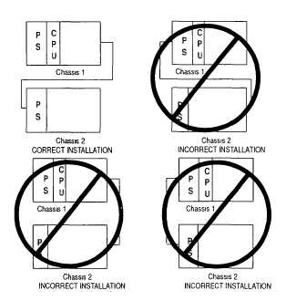
ATTENTION: The expansion cable must always exit the right end of
the chassis with the processor. Refer to the following figures.
(page 3-416)