TM 5-3895-374-24-1
Chapter 5
Installing Your Hardware
Components
2.
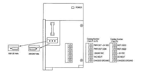
Fasten the power supply to the chassis with the two philips head screws.
3.
Place the jumper to match the input voltage. (This does not apply to 1746-
P3, which does not have a jumper.)
4.
Remove the warning label from the top of the power supply.
5.
Connect line power to the power supply.
ATTENTION: If you have a 1746-P3, see page 2-6 for special
grounding considerations.
On the 1746-P1 and -P2 power supply, use the PWR OUT + 24 VDC and PWR
OUT COM terminals to power sensors. The terminals provide an isolated,
nonfused, 200mA, 24 VDC power supply.
(page 3-415)