TM 5-3895-374-24-1
Options
ALTIVAR 0,75 to 30 kW
Installing the VW3-A45201 D90 option board
Switch off the power and control of the ALTIVAR and wait for the capacitors to discharge (about
5 minutes after switch off, when the LED on the front goes off)
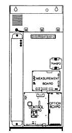
Remove the speed controller’s protective cover
The location intended for the option board is to be found to the right of the control board 3
internal links to J1, J2, J3 and J8 connectors on the option board are fixed to the support plate,
and must be released before mounting the option board
Unplug the removable J5 and J6 connectors from the option board
Take the board, holding it so that the components face the operator, and the connectors face
downwards, via the lower part, slide it onto the two positioning blocks situated in the bottom part
of the location, and then click into position in the upper part
Connections
Connect the option board’s flying leads to the measuring board’s J13 connector
Connect the female connectors of the internal links to the corresponding male connectors on the
board (J1, J2, J3 and J8)
WARNING: attach the connectors without forcing them, making sure that they have been fitted
the right way around, then check that they are correctly fixed
If the speed regulation option is not to be used, do not connect the wire between the option
board’s J5 connector and the control board’s J3 connector
Put the plug-in terminal block back on to the J6 connector
If the motor is fitted with a brake whose windings are accessible via terminals, connect the
contact of the low speed relay available at LA-LB terminals into the control sequence
If the resistance is protected by thermocontact (see following page) connect it to the PY-PZ
terminals
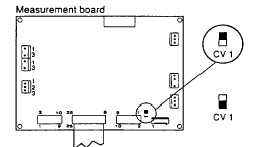
Preliminary checks
A CV1 switch on the measurement board allows the braking resistance thermal protection to be
selected
Use with resistance without
thermocontact
Factory setting
Use with resistance protected by
thermocontact
Put the switch into this position
(Page 3-221)